今天我家兜兜已经9天了。带她到医院去做疾病筛查。搞的我很紧张,早早的就从公司跑了回来。准备了个大包,装了很多东西:奶粉、奶瓶、纸尿裤、开水、冷水…… 结果到了医院才知道,就在小脚牙上采了点血。我们家兜兜就哭了两声就睡着了。前后也没有三分钟,又把大包给背回来了。
兜兜长的还是满快的。虽然没有去称体重,但是我这个天天见的爸爸都觉得她的小脸变大了。身子也结实了许多。对声音也比从前要敏感了。而且在吃奶的时候,还会时不时的笑一下。很是可爱。晚上6点左右吃过后,还会自己在小床上玩一会儿。动动小手小脚,练几个表情,伸伸小舌头,看得我都笑的合不隆嘴了。
现在我已经开始上班了。不能经常在家里照看兜兜了。也不能拍照片了,因为晚上拍出来的效果不太好。看样子要想其他的办法给她多留点记录了。
Monday, October 29, 2007
Thursday, October 25, 2007
我家兜兜第四天

今天我家兜兜已经第四天了。一大早把她迎回了家。小家伙刚回到家,可能有点不太适应,睡的不好。有点哭闹。还好在吃饱后给我抢了个镜头。
小家伙是个大胃王,一次吃奶要50ml。而且很快就会又饿了。有没有人有好的兼职介绍一下给我,好给孩子多歉点奶粉钱。
兜兜变化还是满大的,跟前几天有明显的不同。不过脾气也长了很多。吃的给晚了一点就哭的惊天动地的。
夜里过的还算是安稳,只在3点多的时候起来吃了一次奶。
Designing Finite State Machines (FSM) using Verilog
Designing a synchronous finite state machine (FSM) is a common task for a digital logic engineer. A finite state machine can be divided in to two types: Moore and Mealy state machines. Fig. 1 has the general structure for Moore and Fig. 2 has general structure for Mealy. The current state of the machine is stored in the state memory, a set of n flip-flops clocked by a single clock signal (hence “synchronous” state machine). The state vector (also current state, or just state) is the value currently stored by the state memory. The next state of the machine is a function of the state vector in Moore; function of state vector and the inputs in Mealy.
Fig. 1: Moore State Machine
Fig. 2: Mealy State Machine
Verilog Coding
The logic in a state machine is described using a case statement or the equivalent (e.g., if-else). All possible combinations of current state and inputs are enumerated, and the appropriate values are specified for next state and the outputs. A state machine may be coded as in Code 1 using two separate case statements, or, as in code 2, using only one. A single case statement may be preferred for Mealy machines where the outputs depend on the state transition rather than just the current state.
Consider the case of a circuit to detect a pair of 1's or 0's in the single bit input. That is, input will be a series of one's and zero's. If two one's or two zero's comes one after another, output should go high. Otherwise output should be low.
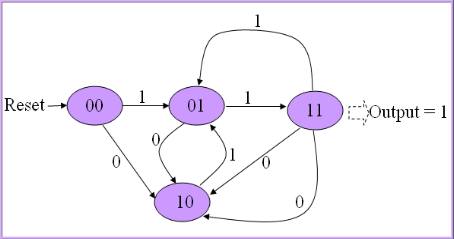
Here is a Moore type state transition diagram for the circuit. When reset, state goes to 00; If input is 1, state will be 01 and if input is 0, state goes to 10. State will be 11 if input repeats. After state 11, goes to 10 state or 01 depending on the inp, since overlapping pair should not be considered. That is, if 111 comes, it should consider only one pair.
Following code the Verilog implementation of the state machine. Note that we updated outp and state in separate always blocks, it will be easy to design. inp is serial input, outp is serial output, clk is clock and rst is asynchronous reset. I have used nonblocking statements for assignments because we use previous state to decide the next state, so state should be registered.
module fsm( clk, rst, inp, outp); |
Here is a testbench that can be used to test all these examples. This testbench generates both directed and random test values. We can specify the sequence in the first part.
module fsm_test; task test2; |
Now, let us re-design the above circuit using Mealy style state machine. Output depends on both state and input. State transition diagram is as follows:
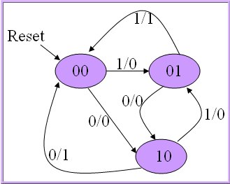
When reset, state becomes idle, that is 00. Next, if 1 comes, state becomes 01 and if 0 comes state becomes 10 with output 0. We have showed input 1, output 0 as 1/0. If input bit repeats, output becomes 1 and state goes to 00.
I implemented this state machine as in the code bellow. Only one always block is used because both outp and state are dependent on state and inp.
module mealy( clk, rst, inp, outp); |
Now, let us discuss difference between Moore and Mealy state machines depending on these codes.
-
Moore state machine is easier to design than Mealy. First design the states depending on the previous state and input. Then design output only depending on state. Whereas in Mealy, you have to consider both state and input while designing the output.
-
Mealy state machine uses less states than the Moore. Since inputs influence the output in the immediate clock, memory needed to remember the input is less. So, it uses less flip flops and hence circuit is simpler.
-
In Mealy, output changes immediately when the input changes. We can observe this point when you simulate the codes above. In Moore example, output becomes high in the clock next to the clock in which state goes 11. So, Mealy is faster than Moore. Mealy gives immediate response to input and Moore gives response in the next clock.
Sequence detector:
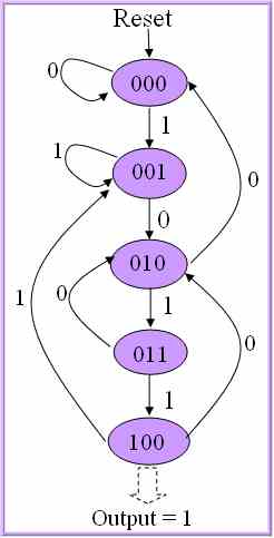
Let us design a circuit to detect a sequence of 1011 in serial input. This is an overlapping sequence. So, if 1011011 comes, sequence is repeated twice. Consider these two circuits. First one is Moore and second one is Mealy. In Moore design below, output goes high only if state is 100. Note that we have used 1 less state than Mealy and hence one flip flop less will be enough to design state machine.
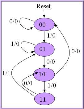
This time I will try to implement only Mealy machine. Try to understand the state diagram and compare them first.
When reset, state goes to 00, where there is no previous inputs. State remains same until we get a '1' in the input since there is no possibility of start of sequence. If a 1 comes in the input, it may be start of sequence, so go to state 01. From 01, if again 1 comes, that means sequence is broken. But there is a possibility of start of another new sequence. So, 01 is start of sequence and stay in the same state. If zero comes, go to state 10.
Another 0 when state is 10 breaks the sequence and state goes to 00, no sequence. If 1 comes, continue to next state 11.
If again 1 comes, sequence completes. Make the output high and go to state 01, because there may be a overlapping sequence as I mentioned earlier. If zero comes, sequence breaks and state goes to 10 since it may be second bit of another sequence.
module m1011( clk, rst, inp, outp); |
This time I combined state and inp using concatenation operator {} to make code smaller. state and inp is used together to select the case. Using this a I avoided if-begin-end-else-begin-end in every case.
Interfaces in SystemVerilog
Connectivity across different design modules in Verilog is accomplished through port connections for each interface signal in instantiations. For large designs, this is not very productive as it involves redundant instances and signal declarations and is prone to error.
To resolve this issue, SystemVerilog adds a powerful interface construct to encapsulate the communication between blocks i.e. multiple signals are grouped together to form a single port. The signals declared in the interface definition is in a single location so that any changes in the interface can be captured accurately modifying only once instead of multiple modules as in Verilog. All the modules using this interface need only declare a single interface type port rather than multiple signals. An example of SV interface is below
SV:
- // AHB Interface Definition
- interface ahb_bus (input logic ahb_hclk, ahb_hresetn); // Interface can have ports.
- // These external signals (hclk, hresetn can be implicitly connected between modules
- wire [31:0] ahb_hdata;
- wire [31:0] ahb_addr;
- logic ahb_hwrite;
- logic [1:0] ahb_htrans;
- logic [2:0] ahb_hsize;
- logic [2:0] ahb_hburst;
- logic ahb_hready;
- logic [1:0] ahb_hresp;
- endinterface
-
- // Top level Module
- module ahb_top (input logic ahb_hclk, ahb_hresetn);
-
- ahb_bus bus (
- .ahb_hclk(ahb_hclk),
- .ahb_hresetn(ahb_hresetn) ); // instance of interface
-
- arm_core arm_inst (
- // ahb_bus ports
- .bus (bus),
- // other ports
- .port1 (port1) // not part of the interface
- ... );
-
- ahb_slave ahb_slave0 (
- .bus (bus) );
-
- dma_master dma_master_inst (
- .bus (bus),
- // Other ports
- ---
- );
-
- on_chip_mem on_chip_mem_inst (
- .bus (bus),
- // Other ports
- --
- );
-
- endmodule
-
- // Module Definitions
- module arm_core (
- ahb_bus bus, // interface port
- // other ports
- input logic port1
- );
- // functionality
- endmodule
-
- module ahb_slave (
- ahb_slave bus
- );
- logic [1:0] ahb_hsel;
- logic [31:0] slave_address;
- // functionality
- // Referring signals inside interface requires using interface port name
- assign bus.ahb_addr = (ahb_hsel == 2'b0) ? slave_address; 'z;
- endmodule
-
- module dma_master (
- ahb_bus bus;
- // Other ports
- ---
- );
- // functionality
- endmodule
An interface can also have tasks, functions, parameters, procedural blocks and type declarations to aid in defining the communication protocol. SV interface cannot have a design hierarchy i.e. no modules can be instantiated in the interface. A modport constructs is provided to define the direction for interface port for different modules. Selecting the appropriate modport for each module can be accomplished during either module definition or during module instance as shown in example below.
SV:
- interface ahb_bus (input logic ahb_hclk, ahb_hresetn); // Interface can have ports.
- wire [31:0] ahb_hdata;
- wire [31:0] ahb_addr;
- logic ahb_hwrite;
- logic [1:0] ahb_htrans;
- logic [2:0] ahb_hsize;
- logic [2:0] ahb_hburst;
- logic ahb_hready;
- logic [1:0] ahb_hresp;
-
- modport master ( inout ahb_hdata,
- output ahb_haddr,
- output ahb_hsize,
- input ahb_hready,
- ---
- );
-
- modport slave ( inout ahb_hdata,
- input ahb_haddr,
- input ahb_hsize,
- output ahb_hready,
- ---
- );
- endinterface
-
- module ahb_top (.. );
-
- ahb_bus bus (...);
- dma_master dma_master_inst (bus.master); // Use the master modport view
- ahb_slave ahb_slave0 (bus.slave); // Use the slave modport view
-
- endmodule
-
- // Alternatively, modport construct can be used in module definition
- module ahb_slave (ahb_bus.master bus);
- endmodule
If no modport is associated with a module, by default all net types are inout and all variable types are ref.
A generic interface port defines the port type using the keyword interface instead of using a name of a specific interface type - the advantage is being able to connect the module to different interfaces. Unlike Verilog, no interface port can be left unconnected and SV .name and .* connection rules can be also be used for interface instances.
SV:
- module ahb_slave (interface bus); // generic interface port
- ahb_slave ahb_slave0 (bus.slave);
SystemVerilog allows tasks and functions to be declared within interface definitions known as interface methods. The task or function has the same syntax as when declared in a module. Using these interface methods, the communication protocol details can be embedded within the interface definition itself.
SV:
- interface ahb_bus (input logic ahb_hclk, ahb_hresetn); // Interface can have ports.
- wire [31:0] ahb_hdata;
- wire [31:0] ahb_addr;
- logic ahb_hwrite;
- logic [1:0] ahb_htrans;
- logic [2:0] ahb_hsize;
- logic [2:0] ahb_hburst;
- logic ahb_hready;
- logic [1:0] ahb_hresp;
-
- // Task defined internal to interface
- task slave_read ( input logic [31:0] raddr);
- // ...
- endtask
-
- endinterface
Interface methods can also be imported if they are not defined within the interface definition itself. If an interface is connected using modport construct, then the import keyword is used to specify the method. Alternative way is to add the task keyword next to the import and also include function arguments - this is required if the task is exported from an external module.
SV:
- interface ahb_bus (input logic ahb_hclk, ahb_hresetn); // Interface can have ports.
- wire [31:0] ahb_hdata;
- wire [31:0] ahb_addr;
- logic ahb_hwrite;
- logic [1:0] ahb_htrans;
- logic [2:0] ahb_hsize;
- logic [2:0] ahb_hburst;
- logic ahb_hready;
- logic [1:0] ahb_hresp;
-
- modport slave ( import slave_read, // simplest way of importing tasks
- inout ahb_hdata,
- input ahb_haddr,
- input ahb_hsize,
- output ahb_hready,
- ---
- );
-
- // Alternative explicit way
- modport slave ( import task slave_read (input [31:0] addr), // explicit
- inout ahb_hdata,
- input ahb_haddr,
- input ahb_hsize,
- output ahb_hready,
- ---
- );
Importing a task or a function through a modport gives the module access to that task by prepending the interface port name to the task name as with other variables. The imported function/task must be declared as automatic in order to be synthesizable.
SV also includes a way to export a task defined in one module to be available to other modules through an interface. For example, if a function is defined in module A and is exported in the modport construct within interface definition using the export keyword, then the task is available to module B that uses that modport. However, this is not synthesizable and we cannot export the same function from multiple instances of a module.
It is also possible to define a task or function using extern keyword without associating it with the modport construct.
SV:
- interface shb_bus (....)
- ---
- extern check_parity (input logic [31:0] data); // Not associated with modport
-
- modport ahb_slave (...);
-
- endinterface
-
- module A (...);
-
- task check_parity (input logic [31:0] data);
- // --
- endtask
- endmodule
Interfaces can also contain procedural blocks like always, always_ff, parameters and generate statements similar to modules.
Casting Strings to Enums in SystemVerilog
Every once and awhile, I want to convert a string to an enumeration in SystemVerilog. Casting from strings to enums is not supported in SystemVerilog, but luckily, it is possible to implement a function to do the appropriate conversion using built in methods designed for iterating over the enum values:
///////////
// enum.sv
///////////
class cmd;
  // My enumerated type
  typedef enum {UNKNOWN, ADD, SUB, MULT} cmd_e;

  // Store the string -> enumerated type mappings.
  static cmd_e enum_map[string];

  // Configure the mapping from string to enum the first
  // time this data structure is created.
  virtual function void config_enum_map();
     cmd_e e;

     string str;
     e = e.first();
     str = e.name();
     enum_map[str] = e;

     // Note - we’ve already processed the first element above. This loop
     // starts at the *second* element.
     for (int i = 1; i < e.num(); i++) begin
        e = e.next();
        str = e.name();
        enum_map[str] = e;
     end

     foreach (enum_map[m]) begin
        $display(”enum_map[%5s] = %5s (%1d)”, m, enum_map[m].name(), enum_map[m]);
     end

  endfunction: config_enum_map

  function cmd_e get_enum(string s);
     get_enum = enum_map[s];
  endfunction

  function new();
     if (enum_map.num() == 0) begin
        config_enum_map();
     end
  endfunction: new

endclass: cmd

program test;
  initial begin
     cmd   c = new;
     cmd::cmd_e ce;

     string s = “ADD”;
     ce = c.get_enum(s);
     $display(”Enum = %s (%1d) for string %s”, ce.name, ce, s);

  end

endprogram
In VCS, run the above code using ‘vcsi -sverilog -ntb_opts dtm -R enum.sv’ to see the following output:
Compiler version VCSi Y-2006.06-SP1; Runtime version VCSi Y-2006.06-SP1;  Oct 21 14:43 2007

enum_map[ADD] = ADD (1)
enum_map[MULT] = MULT (3)
enum_map[SUB] = SUB (2)
enum_map[UNKNOWN] = UNKNOWN (0)
Enum = ADD (1) for string ADD
           V C S   S i m u l a t i o n   R e p o r t
Tuesday, October 23, 2007
我家兜兜第三天
 我们家兜兜第三天了。看起来变化还是很大的。小眼睛不是那么的肿了。而且我看到了她的眼睫毛,短短的,淡淡的。听说应该以后会颜色变深,变长的,期待中。
都说看自己家的宝宝越看越可爱,我也有同感。但是讲老实话,我并不是很在意她的长相,只希望我家兜兜能健健康康地快快长大。
兜兜饿了吃奶的时候,样子实在是太可能。但是为了保护她妈妈的隐私,没有拍摄。想起来就想笑。
吃饿的她,安静地睡在自己的小床里。刚开始一动不动,我有点心慌,去用手感觉一下她是不是还在呼吸。生怕兜兜出任何问题。可是她的呼吸很弱,我没办法感觉到。没办法,只好用手去碰一下她的头,看到她动一下才能放心。我喜欢一直看着她睡觉的样子。皱眉,伸舌头,动动小手,转转头,每一个动作都给我还来欢乐。我想记下她的很一个动作,不想错过任何一秒。
今天兜兜做了听力测试,安全通过。我一点都不担心这一点。出生第一天,她就对声音有很好的反应了。
今天带她去做抚摸按摩。刚开始的时候,她哭的很利害,不知道是什么原因。同房间的别一个孩子正在第一次游泳,孩子的爸爸给他录象,结果里面都是我家兜兜的哭声。可是当对兜兜进行“妈妈家你”按摩的时候,她确变的很安静了,真的很神奇。
我家兜兜第一天
经过30几个小时的等待,我终于等到了我家兜兜的到来。我第一眼看到她的时候是在产房里的。护士跟我讲了她的体重,我都没有听清楚。准备好了手机,想给她拍第一张照片,但是当时激动的我根本就没有反应过来。
我家兜兜:
出生于2007年10月21号11:05. 体重:3618g.
见到她的第一眼,让我忘记了30几个小时没有休息的疲惫。
想的很多,确写不出来。我只希望她能健康成长,尽快听到我对她讲“兜兜,爸爸爱你,永远爱你。”


我家兜兜:
出生于2007年10月21号11:05. 体重:3618g.
见到她的第一眼,让我忘记了30几个小时没有休息的疲惫。
想的很多,确写不出来。我只希望她能健康成长,尽快听到我对她讲“兜兜,爸爸爱你,永远爱你。”


我家兜兜第二天
 今天是我们家兜兜来到这个世界的第二天了。看着这张熟睡的脸,有一种说不出的感觉。
相比昨天的所变化。脸不再那么红了。眼睛肿的不那么利害了。
听到兜兜饥饿时的哭声,太宏亮了。一张小脸憋的通红。眼泪也从眼里流了出来。很是可怜。但是不能打扰他这难得的机会,让她增加一点肺活量。
兜兜奶吃的不多,给她准备的奶粉她看起来不太喜欢,只吃了一小口。吃饱后的兜兜安静的很。自己动动小手,小脚。还有她那唯一自己可以控制的舌头。两只眼睛尽力睁天,跟着声音的方向看着一切新奇的事物(尽管她现在还没有视觉)。
Subscribe to:
Posts (Atom)
