新装的wine中文全是乱码,需要修改一下几个配置文件,找到一篇比较详细的配置说明,分享一下:
步骤:
1. 初始设置
运行 winecfg,把模拟的 Windows 系统设置为 Windows XP 或者 Windows 2000。
2. 准备字体
为了让 Windows 应用程序看上去更美观,所以需要 Windows 下面的字体。
由于我已经将 simsun.ttc 复制到 /usr/share/fonts/windows/ 目录中了。所以我只需要在 ~/.wine/drive_c/windows/fonts/ 目录中为 simsun.ttc 创建一个符号连接:
cd ~/.wine/drive_c/windows/fonts
ln -s /usr/share/fonts/windows/simsun.ttc simsun.ttc
ln -s /usr/share/fonts/windows/simsun.ttc simfang.ttc
创建一个 simfang.ttc 是许多 Windows 应用默认使用 simfang.ttc 字体。
3. 修改 ~/.wine/system.reg
装好字体后,还要修改一下 Wine 的注册表设置,指定与字体相关的设置:
gedit ~/.wine/system.reg
(一定要使用 gedit 或其他支持 gb2312/utf8 编码的编辑器修改这些文件,否则文件中的中文可能变乱码)
搜索: LogPixels
找到的行应该是:[System\\CurrentControlSet\\Hardware Profiles\\Current\\Software\\Fonts]
将其中的:
"LogPixels"=dword:00000060
改为:
"LogPixels"=dword:00000070
搜索: FontSubstitutes
找到的行应该是:[Software\\Microsoft\\Windows NT\\CurrentVersion\\FontSubstitutes]
将其中的:
"MS Shell Dlg"="Tahoma"
"MS Shell Dlg 2″="Tahoma"
改为:
"MS Shell Dlg"="SimSun"
"MS Shell Dlg 2″="SimSun"
4. 修改 ~/.wine/drive_c/windows/win.ini
gedit ~/.wine/drive_c/windows/win.ini
在文件末尾加入:
[Desktop]
menufontsize=13
messagefontsize=13
statusfontsize=13
IconTitleSize=13
5. 最关键的一步,网上很多文章中没有提到的一步──把下面的代码保存为zh.reg,然后终端执行
regedit zh.reg
REGEDIT4
[HKEY_LOCAL_MACHINE\Software\Microsoft\Windows NT\CurrentVersion\FontSubstitutes]
"Arial"="simsun"
"Arial CE,238"="simsun"
"Arial CYR,204"="simsun"
"Arial Greek,161"="simsun"
"Arial TUR,162"="simsun"
"Courier New"="simsun"
"Courier New CE,238"="simsun"
"Courier New CYR,204"="simsun"
"Courier New Greek,161"="simsun"
"Courier New TUR,162"="simsun"
"FixedSys"="simsun"
"Helv"="simsun"
"Helvetica"="simsun"
"MS Sans Serif"="simsun"
"MS Shell Dlg"="simsun"
"MS Shell Dlg 2"="simsun"
"System"="simsun"
"Tahoma"="simsun"
"Times"="simsun"
"Times New Roman CE,238"="simsun"
"Times New Roman CYR,204"="simsun"
"Times New Roman Greek,161"="simsun"
"Times New Roman TUR,162"="simsun"
"Tms Rmn"="simsun"
再winecfg,就可以看到中文能正常显示了。
Monday, April 25, 2011


Tuesday, March 29, 2011
Why use Active-Low reset signal?
Just list some reasons that I think they are correct. Comments are welcome.
1. Board design methods. Usually capacitor circuit is used for Power-On-Reset, such that the voltage at reset pin gradually goes to HIGH value. And by this time all reset activity is done.
2. In CMOS technology, the falling edge of a signal is sharper than a rising one.
3. Library implies.
4. After reset, the reset signal change to high, so the reset signal will not infer by noise.
5. Personal habits
1. Board design methods. Usually capacitor circuit is used for Power-On-Reset, such that the voltage at reset pin gradually goes to HIGH value. And by this time all reset activity is done.
2. In CMOS technology, the falling edge of a signal is sharper than a rising one.
3. Library implies.
4. After reset, the reset signal change to high, so the reset signal will not infer by noise.
5. Personal habits
Tuesday, March 22, 2011
VCS and coverage
As usual I am putting mixed unstructured infromation on yet another tool, this time it is VCS.
I believe that it will provide a lot of practical information for users than the user guides or any other tutorial
provides. Any questions, please write to me at avimit at yahoo dat com.
VCS is 3 step process
1. Analyze (vhdlan vlogan) This command complies the given code and checks for syntax errors.
2. Elaborate ( vcs
3. Simulate ( simv )
While using VHDL design files, a simulaiton file 'synopsys_sim.setup' is usually defined, which defines
the compiled vhdl library.
Example 'synopsys_sim.setup' file:
------------
WORK > DEFAULT
DEFAULT : ./work
memlib : ./mem_lib
xm_bus_lib : ./xm_bus_lib
---------------------------------
The first line maps the WORK library to a name 'DEFAULT', and the second line maps the 'DEFAULT' library
to a physcial directory called './work'.
The second line defines a library memlib which is mapped to a physcial directory called 'mem_lib'.
In the absence of any 'synopsys_sim.setup' file in your working directory, vcs will look for the same file in your home directory,
and if there is no 'synopsys_sim.setup' in your home directory, it will look for the same file in the tool installation directory.
The default 'synopsys_sim.setup' is in the tool installation directory, which maps the default work directory to '.'.
You will see complied VHDL files in '.' in case you dont have a 'synopsys_sim.setup' file.
Example vhdlan commands:
vhdlan -w memlib../../pid_filter/rtl/fun_pkg.vhdl
vhdlan -w work ../vhdl/state_machine.vhd
vhdlan ./state_machine_tb.vhd
Example elaboration commands:
vcs -cm line+cond+fsm+tgl+path pid_filter_tb
This steps generates an executable file which is named simv by default. This name can be changed.
Example simulaiton commands:
simv -ucli -do file.cmds
Contents of a simple file.cmds
---------------
run 1 ms
exit
------------------------------------
simv -gui
simv -cm line+cond+fsm+tgl+path -gui
simv -g generics_file
contents of 'generic_file'
----------------
assign 1 /TOP/LEN
assign "OK.dat" /TOP/G1/vhdl1/FILE_NAME
assign (4 ns) /TOP/G1/VHDL1/delay
assign 16 /TOP/width
assign 4 /TOP/add_width
------------------------------------------
VCS can be a 2 step process if only verilog is being used
vcs
Generating Makefile:
vcs -lca -makedepends=makefile state_machine_tb
It seems that the same above command is used to generate makefile, and to do an incrimental compliation.
Incremental compliation is enabled by default:
VCS commands
removing like ncrm
updating like ncupdate
hierarchy browsing using commands
dump values in a txt file like ncsim
how to define the hierarchy
forcing nets in simulation, syntax.
LEDA:
Latches, linting, cross clock domain checking. Can write the rule in leda.
setenv VCS_HOME <>
set path = ($VCS_HOME/bin $path)
syschk.sh -v : will tell about environment
vcs -doc
command_name -help
The simulation flow:
synopsys_sim.setup : to map logical and physcial libraries
vlogan
vhdlan
vcs
vsim
setenv SYNOPSYS_SIM_SETUP
1 tools setup
2 home
3 current dir
4 $SYNOPSYS_SIM_SETUP
include: not sure.
WORK> logical_name
Example:
WORK > gate_lib
gate_lib : /libs/glib
LIBRARY_SCAN = TRUE | FALSE
ASSERT_IGNORE = NOTE
ASSERT_IGNORE_NOTE
ASSERT_IGNORE_WARNING
ASSERT_IGNORE_ERROR
ASSERT_IGNORE_FAILURE
TIME_RESOLUTION = 10 ps
ASSERT_STOP = NOTE | WARNING | ERROR | FAILURE | NOSTOP
RUNREAD =
run this file automatically when it starts.
show_setup
show_setup -lib
-v means file containing many modules
-y means directories where tech libs are
makedepends
-xlrm
uum : unified use model. $VCS_HOME/doc/uum.pdf
-ucli - Enable Tcl command-line interface
-debug : allows to dump waveforms
-debug_all : line debug
-cm
vcs -makedepends =
gamke makefile
vcs
vcs -debug_pp (post processing)
for tcl and gui
use
vcs -debug
checkpointing:
$vcdpluson
$dumpvars
vcs -debug +memcbk to dump say vhdl record types, which are not dumped by default
initial $sdf_annotate(...);
vcs -sdf=[min|typ|max]:instance_name:
-P $VCS_ROOT/include/hdl_xmr.tab for
hdl_xmr instead of init_signal_spy in modelsim
library synopsys;
use synopsys.hdl_xmr_pkg.all
above to use the signal_spy kinda thing
ncmirror I guess is an eq in cadence.
add_wave /E/UUT/T_BLOCK/HRS_OUT
scope /E/UUT/A_BLOCK
add_wave RESET : will add a wave from A_BLOCK as the scope has been set
-gv
-do instead of -i : because gives more than -i
-i
-gv can also be used with vcs -gv, which will help in changing all generics instead of limited as in vsim -gv
Recommendation: Always analyze verilog first
vcs -cm line : enable line coverage
IF it crashes, to clean up do the following:
rm -rf physcial_lib_dirs/*, simv*, csrc*
OPTIMISE = FALSE -- In synopsys_sim.setup
vcs -gui -debug : only show if compilation is successfull
vcs -debug_pp
vcs -debug_all
vcs -debug=1|2|3|4(level of debug)
simv -gui : preferred way of doing it. I.E first create a executable.
vcs -assert dve -Enable assertion debug
dve -vpd
run -posedge my_sig
restart
help -ucli
help -gui
alias
dump -file
dump -add /tb
dump -add -depth
dump
dump -fid -VPD0 -add * -depth 0
fid is a file identifier returned by command dump -file
add '-aggregates' in the dump command for dumping multi dim arrays
vpd2vcd +morevhdl
+morevhdl will dump 'records' type as well.
//VCS coverage off
//VCS coverage on
vcs -cm
simv -cm
urg : unified report generator
urg -dir ./simv.cm -grade -report ./reports
-------------------------------------
VCS libraries for VHDL compilation
-------------------------------------
VHDL files are compiled into a library.
Usually the default library is 'work' which is mapped to your current working directory i.e "."
Usually you will see that this 'work' library path is changed by defining the work library in synopsys_sim.setup file
WORK > DEFAULT
DEFAULT : ./work_lib
Then other libs may be defined in the same file i.e synopsys_sim.setup file:
memlib : ./memlib
pkg_lib : ./allcompiledpkgs
xm_bus_lib : ./xm_bus_lib
Further observation about vhdl library and vhdl compliation:
vhdlan -work work fun_pkg.vhdl
OR
vhdlan fun_pkg.vhdl
which means that 'fun_pkg.vhdl' is complied into work_lib
when you see the contents of work_lib you will see files FUN_PKG.sim FUN_PKG__.sim
Now I have another file called
xmbus_master.vhd which intends to use 'fun_pkg' package from the work lib
i.e the xmbus_master.vhd has the following lines
use work.fun_pkg.all
now if I compile the xmbus_master.vhd like this
vhdlan -w xm_bus_lib xmbus_master.vhd
I would expect that the complier picks up fun_pkg from work_lib. But it DOESNOT!
Which emplies that 'work' in the statemetn use work.fun_pkg.all refers to the library xm_bus_lib, to which xmbus_master.vhd is being complied into.
On the other hand if I do the following
vhdlan -w memlib fun_pkg.vhdl
Then I use the following lines in xmbus_master.vhd
library memlib;
use memlib.fun_pkg.all;
then I compile xmbus_master.vhd like
vhdlan -w xm_bus_lib xmbus_master.vhd
Then things are FINE, this time the complier picks up complied 'fun_pkg' from the memlib.
So the conclusion is:
when using 'use work.abcd.all', 'work' refers to the current compliation lib given with -w option while compliling the file
containing 'use work.abcd.all' , and NOT to the 'work_lib' which is the default compliation lib
IMP CMDS:
show_setup -lib
show_setup
llib
llib -l pidf
It will show the source file, dependency files
vhdlan options:
-q : quite
-nc : supress the copyright message
-l : log file
VCS OPTIONS:
vcs -debug_all : to enable force/line debug etc.
vcs -o
VCS/Synopsys Code Coverage:
3 Step Process: (after vhdlan or vlogan)
Step 1: Include -cm option during vcs: This step makes sure that the selected code is complied for selected type of coverage
Example:
vcs -cm line+cond+fsm+tgl+path pid_filter_tb
OR
vcs -cm_tgl mda -lca -cm line+cond+fsm+tgl+path -debug_all pidf_tb
OR
vcs -lca -cm line+cond+fsm+tgl+path -debug pidf_tb -cm_tgl mda -cm_hier cm_hier.file
Step 2: Include -cm option during simulation: This Step makes sures that simulator doesnot forget to collect coverage data during simulaiton
Example:
simv -cm line+cond+fsm+tgl+path -gui
Step 3: cmView : for gui based analysis : This Step will let you see coverage results in a GUI
Example:
cmView
Step 3: vcs -cm_pp : for batch mode post processing. This step outputs report files
Example:
vcs -cm_pp -cm_report summary
This will generate human viewable reports in the simv.cm/reports directory.
it also writes a summary file in the same directory, named 'cmView.summary'
vcs -cm line|cond|fsm|tgl|path|branch|assert
Example command
vcs -cm line+cond pid_filter_tb
vcs -cm line+cond+fsm+tgl+path pid_filter_tb
adding -path gives an Error to avoid it use -lca
vcs -lca -cm path pid_filter_tb
And dont forget the -debug, in case you want to see anything : ).
vcs -lca -debug_all -cm line+cond+fsm+tgl+path pid_filter_tb
Still I have to face problems, so the final command line looked like:
vcs -cm_tgl mda -lca -cm line+cond+fsm+tgl+path -debug_all pidf_tb
Now simulaiton may be launched, again all the coverage options given at the 'vcs' compilation
MUST be given to the simv as well or there will be NO coverage recorded.
But then you cant use '-cm_tgl mda'. You see dont apply your common sense, or nothing will work.
After all vcs is developed by Synopsys not Google.
simv -cm line+cond+fsm+tgl+path -gui
NOTES:
-cm option creates simv.cm directory
During Simulation following files are produced:
test.line and test.fsm etc.. depending upon the coverage option.
To over ride the default 'test' name you can use
vcs source.v -cm line -cm_name test1
vcs source.v -cm line -cm_name test2 ...etc
OR
simv -cm line -cm_name test2
simv -cm line -cm_name test3 etc...
Also, during simulation, VCS and VCS MX write the cm.decl_info file
in either the simv.cm/db/verilog directory (for Verilog) or the simv.cm/
db/vhdl directory (for VHDL). cmView needs this file to show
coverage information.
If you invoke your binary executable from a different location, then
use -cm_dir option at runtime to specify the the path for the
coverage database directory
By default VCS does not compile the following for coverage:
• The source code in Verilog library directories
• Verilog library files
• Any module defined under the celldefine compiler directive
yv
For compiling for coverage source code from Verilog libraries.
celldefine
For compiling for coverage modules defined under the
vcs source.v -v mylib.v -y /net/libs/teamlib -cm fsm -cm_libs yv+celldefine
To prevent this lowering of coverage percentages, use the
-cm_noconst compile-time option
Constant filtering for toggle coverage is available only for
Verilog-only designs
simv -cm fsm -cm_log run1.log
Hierarcy in the design, and inclusion/exclusion of modules/files/instances.
-tree instance_name [level_number]
A level number of 0 (or no level number) specifies the entire
subhierarchy, 1 specifies only this instance, 2 specifies this
instance and those instances directly under this instance, and so
on
vcs -lca -cm line+cond+fsm+tgl+path -debug pidf_tb -cm_tgl mda -cm_hier cm_hier.file
cm_hire.file contents
begin
line+cond+fsm+tgl+path -file ../../pid_filter/rtl/fun_pkg.vhdl
end
begin
line+cond+fsm+tgl+path -tree STATE_MACHINE_TB 1
end
Interesting observation
If I miss (all) coverage options on the command line, with this file its an error
If I miss (all) coverage options in the cm_hier.file, its an error.
Various hit and trials:
Works
vcs -lca -cm line+cond+fsm+tgl+path -debug pidf_tb -cm_tgl mda -cm_hier cm_hier.file
simv -cm line+cond+fsm+tgl+path -gui
cm_hier file is:
begin
line+cond+fsm+tgl+path -module pidf
//The above line means exclude line, cond, fsm, tgl, path coverage from module pidf
end
Another example which worked
begin
cond+tgl+path -module pidf
end
I intended to exclude cond+tgl+path, and include the fsm coverage.
The above does write the fsm coverage, since fsm is not excluded from the list inside the cm_hier.file
NOTE: line coverage is always opened for modules or instances that have cond/path/fsm/branch coverage ON.
After several unsuccessfull runs to use '-tree' options, I concluded that it is 'case sensitive', even though i have a VHDL design,
and in my vhdl design pidf_tb, and pidf_u1 are lower case.
For some reason I am required to put the instance name in upper case
Following works
begin
fsm+line -tree PIDF_TB.PIDF_U1
end
BUT the following DoestNOT work.
begin
fsm+line -tree pidf_tb.pidf_u1
end
Now my objective is only to remove the top level testbench from coverage collection. For this I will have to use [level number]
begin
line+cond+fsm+tgl+path -tree PIDF_TB 1
//using level number 1 will make sure only the testbench level is excluded from the coverage collection
end
If I dont use the [level number] in front of PIDF_TB, then by default all scopes under PIDF_TB will be excluded from coverage
This is the same as using level number 0.
PROBLEM: while trying to use the -file option
------------------------
Warning-[VCM-HFUFR] Hier Config: regions not found
In the hier config file ( given by -cm_hier option ), pattern "-file or
specified by -filelist ---
/projects/leota/amittal/block_design_flow_dev/pid_filter/rtl/pidf.vhd" did
not match any pattern.
Please check the hier config file "cm_hier.file".
Warning-[VCM-HFNM] Hier Config: No pattern match
None of the patterns in the hier config file ( given by -cm_hier option )
matched any pattern.
Please check the hier config file "cm_hier.file".
----------------------------------------------------------------------
I have been trying to use -file option and above is the warning message. The corresponding cm_hier.file is
Note that I have used full path for the file I wanted to exclude. This doesNOT work.
---------------
begin
line+cond+fsm+tgl+path -file /projects/leota/amittal/block_design_flow_dev/pid_filter/rtl/pidf.vhd
end
--------------------------------
Now if I use relative path, then vcs does not complain about the file and things go on fine: The corresponding cm_hier.file is
This Does Work.
-------------
begin
line+cond+fsm+tgl+path -file ../rtl/pidf.vhd
end
----------------------------
The HDL Compiler and Behavioral Compiler user can use the
//synopsys translate_off directive in place of the //VCS
coverage off pragma and the
//synopsys translate_on directive in place of the //VCS
coverage on pragma.
The //VCS coverage on pragma enables line coverage after a
//synopsys translate_off directive and a
//synopsys translate_off directive disables line coverage
after a //VCS coverage on pragma.
Similarly the //VCS coverage off pragma disables line coverage
after a //synopsys translate_on directive and a
//synopsys translate_on directive enables line coverage after
a //VCS coverage off pragma.
Pragmas do not exclude module instances. For example:
module test;
reg clk, a;
// Synopsys translate_off
mod1 inst1(a,clk);
// Synopsys translate_on
.
.
.
endmodule
This example does not exclude test.inst1 from coverage
--synopsys coverage_off or --VCS Cover off
--synopsys coverage_on or --VCS Cover on
--vhdlcoveroff
--vhdlcoveron
Glitch supression.
To prevent this, there is the -cm_glitch compile-time option. Its
syntax is as follows:
vcs -cm line+cond+tgl -cm_glitch period
The -cm_glitch option is also a runtime option, but it only works
for toggle coverage
Collecting an Execution Count
-cm_count compile-time option
Post Processing:
vcs -cm_pp -cm_report summary
The above command is used to post process the results of Code Coverage generated during simulaion.
This command produces results in simv.cm/reports directory.
Some more imp commands:
vcs -cm_pp -cm line+cond -cm_report testlists
NOTE:
The graphical user interface (GUI) for cmView does not display
path coverage information. You must have cmView write path
coverage reports
VCS and VCS MX do not monitor the if statement in the for loop
statement and the if statement in the user-defined task
Branch coverage is implemented for Verilog simulation only :(
NOTE:
By default VCS and VCS MX do not monitor for branch coverage if
and case statements and uses of the ternary operator (?:) if they
are in user-defined tasks or functions or in code that executes as a
result of a for loop. You can, however, enable branch coverage in
this code. See “For Loops and User-Defined Tasks and Functions”
on page 4
Assignment Coverage
-cm_line assigntgl compile-time option and keyword argument.
Note:
This is a Verilog-only feature. There is no similar report for VHDL
Glitch suppression does not work for VHDL code
Wednesday, March 9, 2011
Call Google Voice Number with SIP
Say you are wanting to contact your friend, whose Google Voice Number is (555)123-4567. You could now sign up for a free SIP to SIP service, register your account via an SIP app (such as csipsimple or sipdroid), and contact +15551234567@sip.voice.google.com. Doing this would call your friend’s Google Voice number at no cost. The sip.voice.google.com suffix was not previously known to work in any capacity.
Thursday, February 24, 2011
Free Timing Diagram Drawing tools
Many a times we need to generate/draw timing diagrams for multitude purposes. While browsing web for the same I came across these free/easy-to-use timing diagram drawing utilities.
- Timing Diagram Font -- Timing diagram can be generated in MS Word using this
- Timing Analyzer -- A tool for doing the same
- Timing Diagram from verilog - using the above tool and small snippet of verilog code, one can generate timing waveform from the design itself. One problem I see with it is that the code snippet doesn't use verilog macro for achieving the same. Handy Timer - A simple and handy timing diagram editor
- Timing Editor - Another free waveform editor
- Draw Timing - Command line based waveform drawing SW which take a script as its input
Emacs: Start window default size
dit or create ~/.Xdefaults
Put something like this in it:
Save the file. This should make emacs open a window which is 80 characters wide, 30 lines tall, and shifted 0 pixels to the right and 30 pixels down from the upper left corner.
Then in a terminal run:
Launch emacs.
Put something like this in it:
Code:
Emacs.geometry: 80x30+0+30
Then in a terminal run:
Code:
xrdb -merge ~/.Xdefaults
Wednesday, February 9, 2011
fastboot says "< waiting for device >" forever
To be able to use fastboot, you need to be running either an ADP1 or the Engineering Bootloader on your HTC phone.
If you are developing on a linux host, you may need to tweak UDEV to recognize the phone in fastboot mode. You may already have done this to get the phone recognized in Eclipse, but you need to do it again for fastboot, since fastboot uses a different device ID: 0bb4:xxxx. The warning sign is that fastboot says "<>" forever, even when you have the "FASTBOOT" message on the phone; if this happens, try adding the device ID 0bb4:xxxx to your UDEV configuration for Android.
The following config file, in /etc/udev/rules.d/11-android.rules, seems to work:
SUBSYSTEMS=="usb", ATTRS{idVendor}=="0bb4", ATTRS{idProduct}=="xxxx", MODE="0666", OWNER="your login name"
SUBSYSTEMS=="usb", ATTRS{idVendor}=="0bb4", ATTRS{idProduct}=="xxxx", MODE="0666", OWNER="your login name"
NOTE: change "your login name" to your Linux login ID. Also note that the product ID bit is optional (probably easier to leave it out), and you need to change "0bb4" to the vendor ID for your phone if it isn't made by HTC (whose vendor ID is 0bb4). You can find the vendor id using 'lsusb'. An alternative to this is just to run fastboot as root, using sudo.
Wednesday, January 12, 2011
Display Colorful Messages
How many among you know that you can actually display color messages using Verilog and SystemVerilog?
You can implement a logic in your testbench to have nicely colored display messages at the end of your simulation which will give you a PASS/FAIL messages. I have written a piece of code given below and you can refer the same. I have captured a snapshot of output which you can see below.
program clr_display();
class color ;
task display ();
$display("%c[1;34m",27);
$display("***************************************");
$display("*********** TEST CASE PASS ************");
$display("***************************************");
$write("%c[0m",27);
$display("%c[1;31m",27);
$display("***************************************");
$display("*********** TEST CASE FAIL ************");
$display("***************************************");
$display("%c[0m",27);
endtask
endclass
initial
begin
color clr;
clr = new ();
clr.display ();
end
endprogram
OUTPUT:

The message to be printed is ("%c[TYPE;COLOURm",27);.
TYPE specifies how the message should be?
1 set bold
2 set half-bright (simulated with color on a color display)
4 set underscore (simulated with color on a color display)
5 set blink
7 set reverse video
COLOR specifies the message color.
30 set black foreground
31 set red foreground
32 set green foreground
33 set brown foreground
34 set blue foreground
35 set magenta foreground
36 set cyan foreground
37 set white foreground
With an above example you can have a display messages with colors. So this way you can have nicely and colored messages on your terminal.
You can implement a logic in your testbench to have nicely colored display messages at the end of your simulation which will give you a PASS/FAIL messages. I have written a piece of code given below and you can refer the same. I have captured a snapshot of output which you can see below.
program clr_display();
class color ;
task display ();
$display("%c[1;34m",27);
$display("***************************************");
$display("*********** TEST CASE PASS ************");
$display("***************************************");
$write("%c[0m",27);
$display("%c[1;31m",27);
$display("***************************************");
$display("*********** TEST CASE FAIL ************");
$display("***************************************");
$display("%c[0m",27);
endtask
endclass
initial
begin
color clr;
clr = new ();
clr.display ();
end
endprogram
OUTPUT:
The message to be printed is ("%c[TYPE;COLOURm",27);.
TYPE specifies how the message should be?
1 set bold
2 set half-bright (simulated with color on a color display)
4 set underscore (simulated with color on a color display)
5 set blink
7 set reverse video
COLOR specifies the message color.
30 set black foreground
31 set red foreground
32 set green foreground
33 set brown foreground
34 set blue foreground
35 set magenta foreground
36 set cyan foreground
37 set white foreground
With an above example you can have a display messages with colors. So this way you can have nicely and colored messages on your terminal.
Monday, December 20, 2010
在SDK 2.2模擬器中安裝Market
1. 建立AVD,名稱為DAVID_2.2
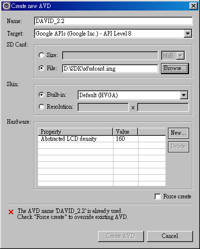
2. 執行「開始—執行—cmd」,預設會在這個資料夾:
C:\Documents and Settings\%HOME%>
3. 切換目錄至「.android/avd/DAVID_2.2」,指令參考如下:
C:\Documents and Settings\David.Lanz>cd .android
C:\Documents and Settings\David.Lanz\.android>cd avd
C:\Documents and Settings\David.Lanz\.android\avd>cd DAVID_2.2.avd
畫面結果:
C:\Documents and Settings\David.Lanz\.android\avd\DAVID_2.2.avd>

4.複製SDK裡的system.img至此,指令如下:
copy d:\sdk\android\platforms\android-8\images\system.ing
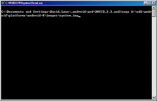
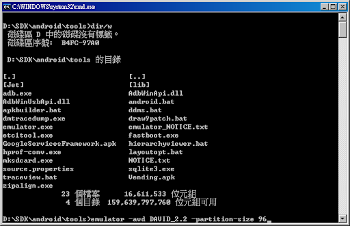
5.在DOS視窗中切換目錄至SDK的tools資料夾,手動啟動模擬器,指令:
cd d:\sdk\android\tools\
emulator -avd DAVID_2.2 -partition-size 96
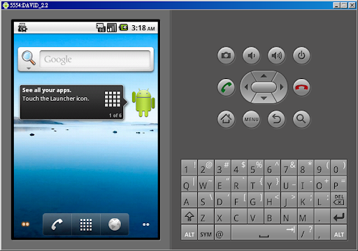
順利執行模擬器畫面
6.在DOS視窗裡執行指令,取出build.prop檔案。
adb pull /system/build.prop

7.利用文字編輯器開啟編輯build.prop這個檔案,將 ro.config.nocheckin=yes 移除(再最前面加上 mark 符號 #)

8.將剛才取出修改好的檔案存檔,然後執行以下指令將檔案放回去。
adb remount
adb push build.prop /system
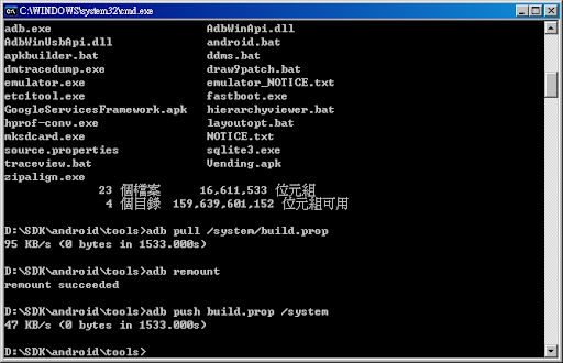
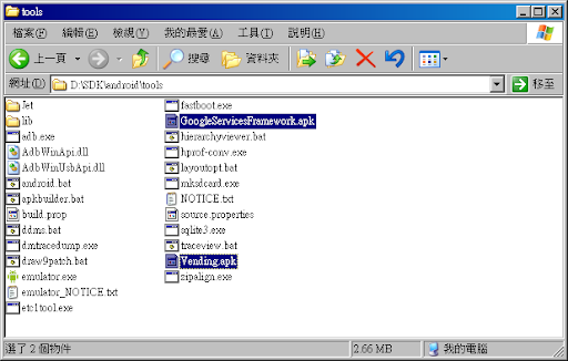
9.至此下載Froyo用的Market程式,將之解壓縮後,存放至SDK資料夾(舉例如下):
D:\SDK\android\tools\GoogleServicesFramework.apk
D:\SDK\android\tools\Vending.apk
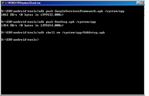
10.將步驟9的兩個apk檔案丟入模擬器/system/app資料夾,並刪除SdkSetup.apk,指令如下:
adb push GoogleServicesFramework.apk /system/app
adb push Vending.apk /system/app
adb shell rm /system/app/SdkSetup.apk
11.關閉 Emulator(直接關閉模擬器的視窗即可)。
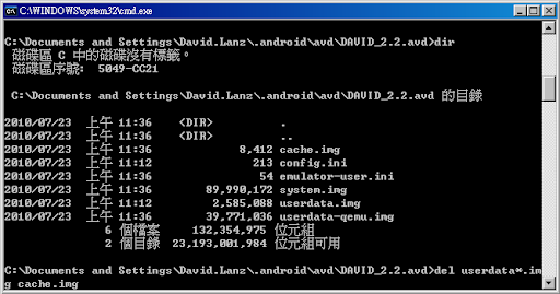
12.切換目錄至avd的資料夾下:
C:\Documents and Settings\%HOME%\.android\avd\DAVID_2.2.avd>
執行以下指令,刪除由系統產生的「userdata-qemu.img」與「userdata.img」、「cache.img 」這三個檔案刪除,讓Emulator完成初始化。
del userdata*.img cache.img
13.執行「Android SDK and AVD Manager」來啟動模擬器。

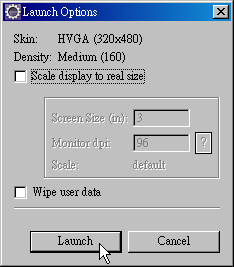

大功告成,Market順利在模擬器裡執行。第一次執行Market必須要以google帳號登入,登入後即可下載程式囉。
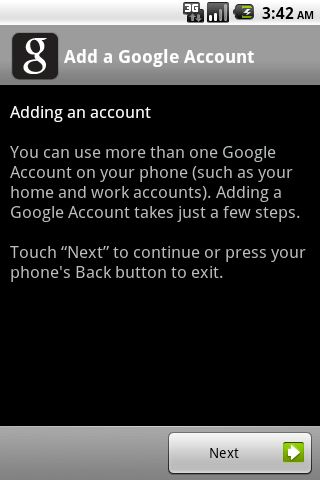


I can install the market, but I can't install App from it. Maybe someone can help me.
2. 執行「開始—執行—cmd」,預設會在這個資料夾:
C:\Documents and Settings\%HOME%>
3. 切換目錄至「.android/avd/DAVID_2.2」,指令參考如下:
C:\Documents and Settings\David.Lanz>cd .android
C:\Documents and Settings\David.Lanz\.android>cd avd
C:\Documents and Settings\David.Lanz\.android\avd>cd DAVID_2.2.avd
畫面結果:
C:\Documents and Settings\David.Lanz\.android\avd\DAVID_2.2.avd>

4.複製SDK裡的system.img至此,指令如下:
copy d:\sdk\android\platforms\android-8\images\system.ing
5.在DOS視窗中切換目錄至SDK的tools資料夾,手動啟動模擬器,指令:
cd d:\sdk\android\tools\
emulator -avd DAVID_2.2 -partition-size 96
順利執行模擬器畫面
6.在DOS視窗裡執行指令,取出build.prop檔案。
adb pull /system/build.prop

7.利用文字編輯器開啟編輯build.prop這個檔案,將 ro.config.nocheckin=yes 移除(再最前面加上 mark 符號 #)

8.將剛才取出修改好的檔案存檔,然後執行以下指令將檔案放回去。
adb remount
adb push build.prop /system
9.至此下載Froyo用的Market程式,將之解壓縮後,存放至SDK資料夾(舉例如下):
D:\SDK\android\tools\GoogleServicesFramework.apk
D:\SDK\android\tools\Vending.apk
10.將步驟9的兩個apk檔案丟入模擬器/system/app資料夾,並刪除SdkSetup.apk,指令如下:
adb push GoogleServicesFramework.apk /system/app
adb push Vending.apk /system/app
adb shell rm /system/app/SdkSetup.apk
11.關閉 Emulator(直接關閉模擬器的視窗即可)。
12.切換目錄至avd的資料夾下:
C:\Documents and Settings\%HOME%\.android\avd\DAVID_2.2.avd>
執行以下指令,刪除由系統產生的「userdata-qemu.img」與「userdata.img」、「cache.img 」這三個檔案刪除,讓Emulator完成初始化。
del userdata*.img cache.img
13.執行「Android SDK and AVD Manager」來啟動模擬器。


大功告成,Market順利在模擬器裡執行。第一次執行Market必須要以google帳號登入,登入後即可下載程式囉。

I can install the market, but I can't install App from it. Maybe someone can help me.
Tuesday, December 7, 2010
Change your Network Card MAC Address on Ubuntu
There are a lot of reasons you might want to manually set your MAC address for your network card. I won’t ask you what your reason is.
To change this setting, we’ll need to edit the /etc/network/interfaces file. You can choose to use a different editor if you’d like.
sudo gedit /etc/network/interfaces
You should see the line for your network interface, which is usually eth0. If you have dhcp enabled, it will look like this:
auto eth0
iface eth0 inet dhcp
Just add another line below it to make it look something like this:
auto eth0
iface eth0 inet dhcp
hwaddress ether 01:02:03:04:05:06
Obviously you would want to choose something else for the MAC address, but it needs to be in the same format.
sudo /etc/init.d/networking restart
You will need to restart networking or reboot to take effect.
Subscribe to:
Posts (Atom)
